(Price doesn't include high voltage PSU)
We describe a very simple laser: no special gas, no chemical products, no vacuum and no glass work!
This Nitrogen laser uses normal air at atmospheric pressure. All you need is some metal parts and an about 10 kV 1 mA adjustable High tension DC source.
(All dimensions in mm)
Brief description:
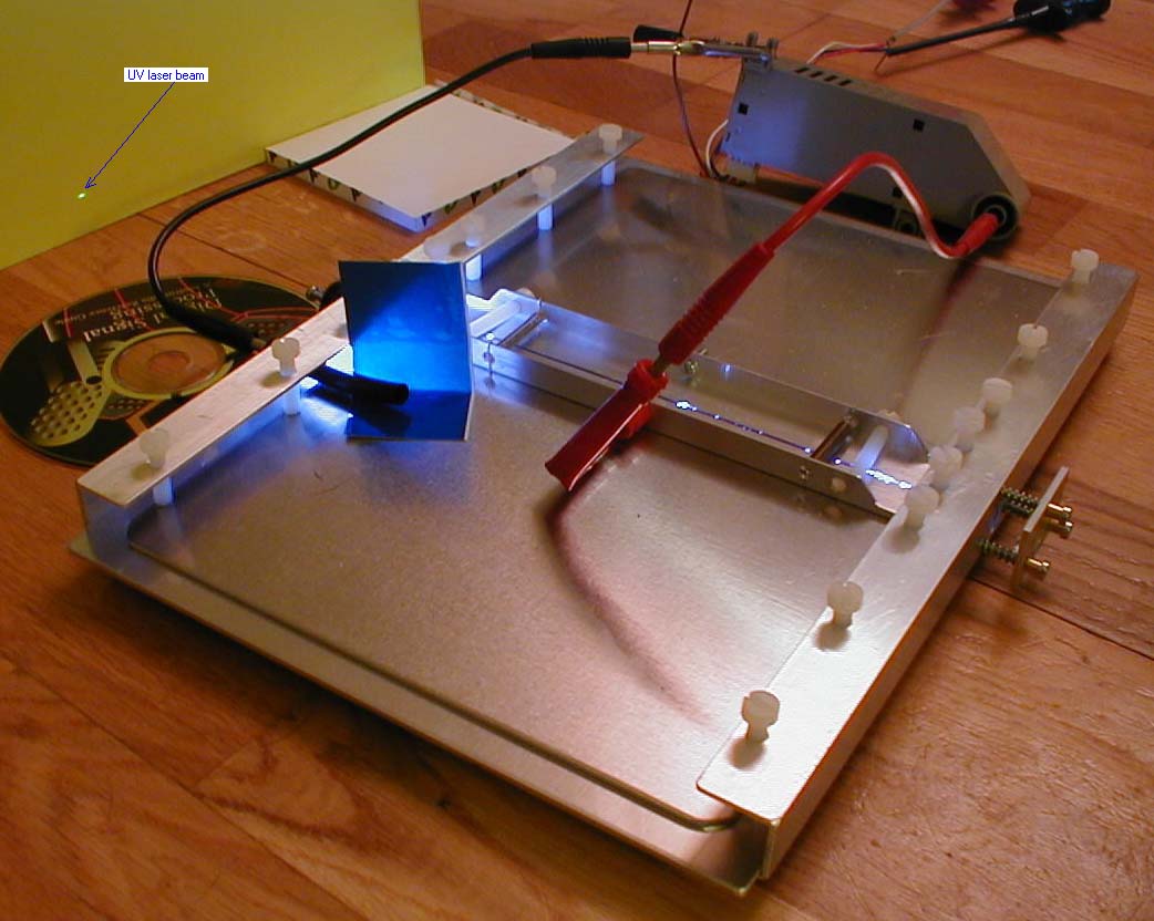
The whole air laser is based on a rectangular A4 aluminium plate on which is disposed a rectangular A4 plastic sheet (European standard paper A4 dimensions 210 x 297 mm). 2 aluminium plates act as capacitors and 2 other pieces of metal (L) are used as electrodes for plasma channel. 2 U aluminium parts screwed on the main plate can hold all that with Nylon screws.
Nylon screws get electrical insulation and allow user to very easily change, modify or adjust plates, electrodes or plastic film.
A4 plastic film is a low cost very easy to find/repair dielectric solution.
Theory:
In fact, this air laser is a Nitrogen laser which use Nitrogen molecules in air to lase. Ordinary Nitrogen laser uses low pressure wide channel nitrogen like the old very well known "American Scientist" Nitrogen laser project: http://www.montagar.com/~patj/n2lmnu.htm
When a high current electric discharge passes through Nitrogen gas at low pressure, it can generate a coherent radiation at the wavelength of 337.1 nm (UV). The laser action begins when a molecule of Nitrogen absorbs energy by colliding with an electron that moves in the discharge. Molecule becomes in an unstable state and spontaneously falls to a state of lower energy by emitting a photon of radiation at 337.1 nm. The emitted photon may encounter another excited molecule of Nitrogen and merely by its proximity stimulate the molecule to emit an identical photon. The two particles of radiation proceed in the same direction with their waves lockstep. This is the laser action. It will continue as long as the growing pulse encounters more excited molecules of Nitrogen along its path that it does absorbing molecules. In the case of Nitrogen, the molecules on the average linger at a lower level longer that at the upper one before moving on to still lower states. The number of molecules at the lower laser level builds up rapidly, exceeding the number at the upper level and terminating the amplification. In fact, the gas quickly becomes strongly absorbing to 337.1 nm emission. The laser turns off even thought there are still excited molecules left. The turn off time is usually less than 10 ns.

That means that the maximum of energy must arrive in the very first ns. The laser structure must be very fast, avoiding parasitic resistors and mainly parasitic inductance. Using air at normal pressure is more difficult: Oxygen atoms tend to prevent laser emission. Normal pressure means low impedance and low width laser channel. That means that the laser structure must be faster.
Most Nitrogen lasers use Blumlein structure (this one also): 2 high tension capacitors (almost identical), one pole connected to ground and the other pole to an electrode. The 2 electrodes are connected together through a self and charged at a high tension. A spark gap is installed on an electrode: when tension is high enough, an arc occurs: a conductive plasma discharges very quickly one capacitor. One capacitor is about to ground, the other is still at a high potential. The huge tension difference between the 2 electrodes produces a plasma which induce laser beam. Then laser beam turns off, plasma stops and, later, other capacitor is discharged through the self. Then all that is charged again though high tension PSU (Power Supply Unit) and the process start again. That means that the structure must be fast enough to be able to deliver most of the energy in the very first ns: The spark gap capacitor fall time must be very low: parasitic resistors and inductors must be at the minimum.
Calculus:
(Here, we are just looking for orders of magnitude, not precise results)
On this prototype, we can consider that high tension is about 10 kV, each capacitor is about 2 nF (measured), "measured" spark capacitor fall time is about 11 ns, probably a little bit less.
CV=it: i=CV/t: 10 000 x 2 10-9 / 10 10-9 = 2000 A : a 2000 A current sink through spark gap for a few ns !
Total parasitic resistors must induce less than 1 kV to be negligible (compared with 10 kV): U=RI: R=U/I: 5 ohms which is easy to realise: parasitic resistors are not a problem (using copper, aluminium or iron isn't very important)
Total parasitic inductors V=Ldi/dt: L=V/(di/dt): 5 nH which is very little, L=u S n2/ l : S= L l / u n2, l=5 mm, u(air)=4 PI 10-7, n=1, =>20 10-6m2 => 20 mm2 is about 5 x 5 mm
That means that a conductor (spark gap connection for example) 5 mm width and 5 mm length to return to ground has an inductor that is not negligible! Parasitic inductors ARE a problem.
Global Nitrogen structure must be very flat and must keep spark gap connection to ground and capacitor, electrode connection to capacitor parasitic selfs at the minimum: loops area must be minimum.
One says there is a "travelling wave" in the capacitor during discharge. In those little amateur lasers, I don't think so. Anyway, accurately and safely measuring such high-tension very fast phenomena is difficult. You must own a fast oscilloscope and a very fast HT probe or using the ILS low-tension trick or a one turn self safely coupled to the Blumlein self
Structure:
We choose a structure simple to build, with very low parasitic inductor, easy to change and adjust: changing the plastic film, a capacitor plate, electrode or adjusting electrode distance is very easy. We use an A4 (210 x 297 mm European standard) main aluminium plate on which we dispose an A4 plastic film, and the 2 capacitor plates. We also install 2 U aluminium rules with nylon screws to press capacitors and electrodes that are L aluminium rules. The 2 electrodes are attached with 2 pull springs that act also as self. 2 nylon screws set distance.
To adjust electrodes distance, simply unscrew a little bit 2 U rules corresponding nylon screws, then adjust distance with the 2 horizontal screws. Once distance OK, screw again the 2 U rules corresponding screws.
A hole in each U rule allows laser to output on one side and to install a 3 screws + springs adjustable mirror on the other side.
Even if this project seems very simple, dimensions has been optimised: I recommend to build the project "as this" before trying to modify parameters.
Bill of material:
- One 210 x 297 aluminium plate (1.5, 2 or 2.5 mm thick)
- One 210 x 297 A4 plastic film (those for printer slide)
- Two 135 x 190 aluminium plates (1.5, 2 or 2.5 mm thick)
- Two 20 x 20 x 250 U aluminium extruded rules
- Two 10 x 20 x 250 L aluminium extruded rules
- Twelve M5 x 20 (or 25 or 30) Nylon screws (or M4 x 20)
- Four metal M3 x 10 screws (chamfered head) with corresponding nuts
- Some M3 metal screws and springs (4 push springs and 2 pull springs)
- Four rubber feet
- One Red + one Black ordinary connectors
- Some 1 Mohms 1W resistors (depending from PSU)
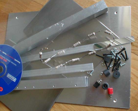
Picture: (CD is just for the scale, these temporary M3 plastic screws are not strong enough)
Construction: (timing is for best understood, not for best efficiency ;-)
- Drill 4 holes d = 3.2 in the main 210 x 297 plate: 2 along one 297 side, 2 along the other 297 side at 10 from side, chamfer it for chamfered screws (screw heads must disappear in the plate to avoid disturb plastic sheet)
- Drill 2 holes d = 3.2 in each U rule and attach U rules on the big side of the main plate with the 4 rubber feet
- Drill 1 hole d = 10 in the middle (vertical face) of each U rule for laser outputs
- Drill 8 holes d = 4.0 on the upper side of each U rule and screw it for M5 screw
- Dispose the A4: 210 x 297 plastic film on the main plate
- Round (r = 5) the two 135 x 190 other plates corners and install it on main plate at 10 from all borders
- Dispose the 2 10 x 20 L rules on the plates in a symmetrical way: ( |__ __| ). Distance: 1 mm
- Install 8 M5 x 20 Nylon screws in each U rule and screw it to press plates and L electrodes
- Chamfer L rules side at 10 to increase distance between L rule and U rule at minimum 10 mm
- In a U rule, drill a 2.3 hole and screw it for M3, install a M3 x 20 screw with a push spring: that's the spark gap. Set it at 5 mm
- In a U rule, drill two d = 6.0 holes, install the Black connector without insulation: the ground connection
- Drill 4 d = 4.0 holes and 1 d = 6.0 in one electrode (and screw 2 holes at M5) and 3 d = 6.0 in the other.
- Install 2 pull springs, 2 M5 x 20 plastic screws and 1 Red connector on electrodes (Nota: pull springs act also as electrical self)
- Connect 5 x R 1 Mohm 1 W resistors between Red connector and electrode (in a clear plastic tube)
-You can also add three M3 holes in a U rules around one hole output and install a little plate with a glued mirror and 3 M3 x 10 screws and 3 push springs. Adjust screws to align mirror optical axis and plasma channel (with you eye or a little red laser pointer)
Nota: How to align mirror: take a white paper sheet, make a 1 mm hole in the middle. Disconnect and discharge laser. Look through the paper hole to the mirror through the laser output hole. Align your eye with electrodes and adjust mirror screws until paper hole is just centred between the 2 electrodes.
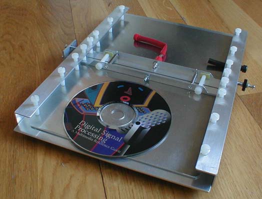
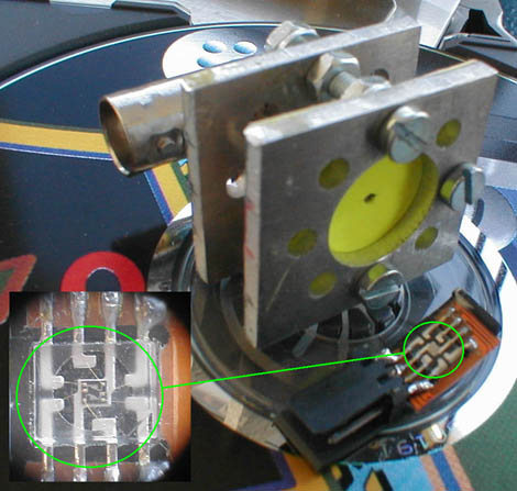
Picture: (CD is just for the scale, at left: mirror with 3 screws and 3 springs to adjust it, electrodes with 2 pull springs, nylon screws and Red HT connector, on the right: spark gap screw with a Black plastic disc)
Preliminary low tension tests:
On that prototype, capacitors are about 2 x 2 nF.
Safely powered with 10 VDC (only), spark gap "replaced" with an ILS switch triggered with a magnet, measured fall time on spark electrode is about 11 ns, fall time on self electrode (other) is about 60 ns. Self electrode fall time and period depends only from capacitor and self value. Here self is made with the 2 electrodes springs, anyway self value isn't very critical.
Picture: In grey the 2 electrodes tension, in black the difference between the two electrodes. Laser will work only during the first ns: between cursors. Sine wave is due to C capacitor and L inductor combination.
HT (High tension) test:
Your laser is now ready to operate! You must connect HT supply set at 10 kV. Now, be very careful; take care to high tension and laser emission. Once laser disconnected, capacitors can keep high tension for a long time. Safely discharge it (with an insulated screwdriver first connect to ground and then to electrode) before touching anything. Or better, take the habit to short-circuit the Black and Red connectors when not powering. (Black connected first then Red)
Once distance between electrodes set to 1.3 mm, spark gap distance set to 3 mm and tension set to 10 kV for a first test. Install a white paper sheet aligned with the laser output at some 500 mm from the output. Put a plastic blackbox on the spark gap, keep away and power on.
If anything is correct, spark gap occurs several times a second (10 Hz for example), you can see a purple plasma band between electrodes without (too much) white sparks. And a white point (about 4 x 1 mm ellipse) appears on the white paper.
Picture: Here laser power is low: this is preliminary HT test, HT is low and everything must be adjust. HT is only an old photocopier 5.5 kV module, electrodes distance is set to 1.25 mm, rear mirror is installed, it has been adjust with the eye though a 1 mm hole in a paper sheet disposed at the laser output hole (when laser was disconnected of course!)
Laser works also without mirror but at lower output power
Of course, you can't see the UV 337.1 nm laser output but you can see the corresponding fluorescence on the white paper.
Once adjusted, any electrical sparks make a spot.
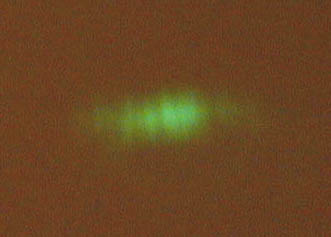
When paper sheet is disposed at 1 m from laser output, characteristic laser interference fringes are visible in the spot.
In this picture, sheet is at 2 m from laser and spot is about 10 x 30 mm, tension is about 10 kV
You can now modify parameters trying to get the strongest light.
In case of problem:
- Be very careful with L electrode side used for plasma: shape must be round and surface must be perfectly line and smooth.
- The 2 electrodes must be perfectly // and at the right distance. I recommend using calliper or car spark plugs adjustment tools: those little iron plates from various thickness. You can also use a CD that is 1.2 mm thin. If electrodes are not //, you see more white sparks at the end where there are nearest: you must then adjust nylon screw to correct it.
Comments and improvements:
- The same laser can be realised bigger to improve output power
- Of course, using Nitrogen instead air will also increase laser output power (far more boring and expensive too :-)
- At atmospheric pressure, air (Nitrogen laser) channel width is little and pumping a dye with it (for visible laser) may be difficult. (I will try soon)
- Adding an insulated plate or wire // and just upper laser channel that acts as a Corona can perhaps stabilise plasma, decrease white sparks and increase efficiency.
- Adding a probe made with and old CD player phototransistor connected to the scope will help to improve laser and increase output power. Of course, phototransistor isn't fast enough to show optical output pulses but stronger the displayed pulse is and stronger the optical output is. (With my CD player phototransistor sample, short wave bandwidth phototransistor is enough to measure 337 nm Nitrogen pulse laser).
This probe use an old CD player phototransistor, all outputs are connected in // and to a 22 ohms resistor: a fluorescent yellow paper with a little hole in front of the phototransistor make position adjustment easy.
Then probe is installed in front of the laser output (well, a luxurious 150$ PSU for a poor 10$ laser!)
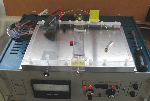
Measurement: Of course, probe isn't fast enough: probe rise time is low: about 300 ns and fall time very low: some us. But higher is the electrical pulse and higher is the optical pulse: we are now able to precisely optimise laser!
- I think that a fast high tension simple and safe probe (capacitor divider) can be built to allow user to measure real capacitors tension without burning the scope. A 50 x 50 mm rectangular aluminium plate which will act as a capacitor with ground. Adding a very little well insulated plate against one electrode, connect the little plate to the 50 x 50. One will make a high tension capacitor attenuator that we can connect to a scope probe.
http://spt06.chez-alice.fr/00/lasers.htm
Any comments?
E-mail :

03/06/05.